Receptacle Wiring Diagram Examples / Solar Panel Wiring Diagram Example : This pictorial diagram shows us the.. You can always replace a standard receptacle with a gfci receptacle. Electrical wiring should be performed by a licensed, trained electrician and should comply with the. A wiring diagram is a simplified conventional pictorial representation of an electrical circuit. Green or uninsulated grounding wire. Some european wiring diagrams are available also.
Receptacles 1 circuit split circuit 1 circuit. Including lighting, engine, stereo, hvac wiring diagrams. The diagram will show how a standard switched duplex receptacle is wired. Once you get your free wiring diagrams, then what do you do with it. It shows how the electrical wires are interconnected and can also show where fixtures and components may be connected to the system.
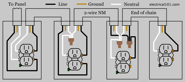
Outlet Wiring Electrical 101 from www.electrical101.com A simplified conventional pictorial representation of an electrical circuit. Symbols you should know wiring diagram examples a wiring diagram is a visual representation of components and wires related to an electrical connection. Take care of every detail. In this diagram, both top and bottom receptacles are switched off & on. You still need to fix the problem that led you here in the first. Wiring a receptacle (also referred to as an outlet) is another of those fundamental wiring skills that every diyer should feel comfortable undertaking. Components of receptacle wiring diagram examples and a few tips. Including lighting, engine, stereo, hvac wiring diagrams.
It shows how the electrical wires are interconnected and can also show where fixtures and components may be connected to the system.
How to wire up an electrical receptacle in one of two methods: Some european wiring diagrams are available also. Grounded and ungrounded duplex outlets, ground fault circuit interrupters (gfci), 20amp, 30amp, and 50amp receptacles for 120 volt and 240 volt circuits. You can always replace a standard receptacle with a gfci receptacle. This article and detailed wiring diagram explains the steps to wiring the common household receptacle/outlet. Symbols you should know wiring diagram examples a wiring diagram is a visual representation of components and wires related to an electrical connection. Including lighting, engine, stereo, hvac wiring diagrams. 15a, 20a, 30a, 50a, 120v and 240v outlet wiring. The diagram will show how a standard switched duplex receptacle is wired. Take care of every detail. Wiring diagrams with conceptdraw diagram. In this diagram, both top and bottom receptacles are switched off & on. Wiring diagram a wiring diagram shows, as closely as possible, the actual location of all component parts of the device.
This article and detailed wiring diagram explains the steps to wiring the common household receptacle/outlet. A wiring diagram is a simplified conventional pictorial representation of an electrical circuit. Once you get your free wiring diagrams, then what do you do with it. This should go without saying but always. Including lighting, engine, stereo, hvac wiring diagrams.
Wiring A Gfci Outlet With Diagrams Pro Tool Reviews from cdn.protoolreviews.com It shows the components of the circuit as simplified shapes, and how a wiring diagram usually gives more information about the relative position and arrangement of devices and terminals on the devices. Residential electric wiring diagrams are an important tool for installing and testing home electrical circuits and they will also help you understand how electrical devices are wired and how various electrical devices and controls operate. Grounded and ungrounded duplex outlets, ground fault circuit interrupters (gfci), 20amp, 30amp, and 50amp receptacles for 120 volt and 240 volt circuits. The diagram offers visual representation of a electrical arrangement. Section 11 wiring diagrams subsection 01 (wiring diagrams). This page contains wiring diagrams for most household receptacle outlets you will encounter including: Diagrams will show receptacles, lighting, interconnecting wire routes, and electrical services within a home. Take care of every detail.
A good wiring diagram needs to be technically correct and clear to read.
Once you get your free wiring diagrams, then what do you do with it. A wiring diagram is a simple visual representation of the physical connections and physical layout of an electrical system or circuit. Receptacles 1 circuit split circuit 1 circuit. A wiring diagram is a type of schematic that uses abstract pictorial symbols to show all the interconnections of components in a system. Wiring a receptacle (also referred to as an outlet) is another of those fundamental wiring skills that every diyer should feel comfortable undertaking. 15a, 20a, 30a, 50a, 120v and 240v outlet wiring. A simplified conventional pictorial representation of an electrical circuit. How to wire up an electrical receptacle in one of two methods: You still need to fix the problem that led you here in the first. Included at the end of the article is a. In this diagram, both top and bottom receptacles are switched off & on. Unlike single line diagrams, every drawn line matches one single wire which. It shows the components of the circuit as simplified shapes, and how a wiring diagram usually gives more information about the relative position and arrangement of devices and terminals on the devices.
It shows the components of the circuit as simplified shapes, and the power and signal connections between the devices. Some european wiring diagrams are available also. Prior to installing a connector, make sure locking tab. A simplified conventional pictorial representation of an electrical circuit. You can always replace a standard receptacle with a gfci receptacle.
Wiring Diagrams For Electrical Receptacle Outlets Outlet Wiring Wiring A Plug Home Electrical Wiring from i.pinimg.com A wiring diagram is a simple visual representation of the physical connections and physical layout of an electrical system or circuit. Prior to installing a connector, make sure locking tab. Diagrams will show receptacles, lighting, interconnecting wire routes, and electrical services within a home. A wiring diagram is a type of schematic that uses abstract pictorial symbols to show all the interconnections of components in a system. The diagram is not meant as a guide for doing wiring; A wiring diagram is a simplified conventional pictorial representation of an electrical circuit. With this sort of an illustrative guide, you. Almost everyone has experience wiring a gfci outlet (ground fault circuit interrupter).
Prior to installing a connector, make sure locking tab.
A good wiring diagram needs to be technically correct and clear to read. Residential electric wiring diagrams are an important tool for installing and testing home electrical circuits and they will also help you understand how electrical devices are wired and how various electrical devices and controls operate. Unlike single line diagrams, every drawn line matches one single wire which. Free wiring diagrams for your car or truck. Wiring diagrams are used to show control and signalization principle of operation inside switchboard. Prior to installing a connector, make sure locking tab. Section 11 wiring diagrams subsection 01 (wiring diagrams). Grounded and ungrounded duplex outlets, ground fault circuit interrupters (gfci), 20amp, 30amp, and 50amp receptacles for 120 volt and 240 volt circuits. Green or uninsulated grounding wire. Wiring a receptacle (also referred to as an outlet) is another of those fundamental wiring skills that every diyer should feel comfortable undertaking. Selector switch and start push button. Jpg for example, a property builder would want to read the physical location of electrical outlets and. Schematic electrical wiring diagrams are different from other electrical wiring diagrams because they show the flow through the circuit rather than the physical layout of any equipment.