Speaker Protection Circuit Diagram / Dc Protection Time Delay For Loudspeaker Circuit Diagram And Instructions / Home/audio circuit diagrams/complex speaker protection circuit schematic circuit diagram.. When any dc voltage detects on the circuit suddenly the circuit get off and protect the speaker protection board working based on the transistors of c9013 and two 945 npn transistors, when any dc signals detect on the input of output. Dc speaker protection, light bulb speaker protection, loudspeaker protection, ptc speaker protection, speaker protection circuit. Speaker protector electronic circuits and diagrams electronic. The positive output of the amplifiers loudspeakers is connected to the relay's entrance and its output is connected to baffle.the power of this circuit is. If the amplifier got any problem then this circuit can save our soundbox.
⇒ values on the circuit diagram are subject to changes. • the speaker protection circuit requires an auxiliary voltage to be provided from a winding of the mains transformer, the value of this voltage should be between 9v ac to 12v ac. The circuit also includes a mute function, which leaves the speakers disconnected until the this article, including but not limited to all text and diagrams, is the intellectual property of rod. This circuit uses center tap transformer and the power supply circuit design already provided in the schematic diagram. ‹ 2 led cmos flasher circuit diagram.
Amplifier Loudspeaker Overload Protector Circuit from makingcircuits.com We can increase the delay even more if we increase the value of c1. Nice to meet you, now you are in the wiring diagram carmotorwiring.com website, you are opening the page that contains the picture wire wiring diagrams or schematics about speaker circuit diagram. Speaker protection circuit is simple yet practical to use. ⇒ values on the circuit diagram are subject to changes. The given amplifier short/overload protection circuit diagram, shows an inexpensive i have made a 150 watt mosfet stereo amplifier and i was searching for a good, simple short circuit protection circuit for this amp , i only found protection circuit for speakers in your blog and i have added it. This circuit is made to protect the. Circuit, diagram, overload, protection, speaker. The speaker protection circuit of the illustrated em bodiment of the invention and the ampli?er 10 to which is connected are both powered by a power sup 5 time, the voltage across capacitor c7 gradually builds up from zero volts to about 30 volts.
Electronic coin toss circuit diagram ›.
This is the schematic diagram of 35w bridge power amplifier circuit, delivers 35w power output for 8? When any dc voltage detects on the circuit suddenly the circuit get off and protect the speaker protection board working based on the transistors of c9013 and two 945 npn transistors, when any dc signals detect on the input of output. Dc speaker protection, light bulb speaker protection, loudspeaker protection, ptc speaker protection, speaker protection circuit. Speaker protector circuit with dc protection. How to make speaker protection with ksd301 90c thermostat temperature control switch at home. Consequently, the ply 32 which is turned on and off by a. ⇒ position all parts on the pcb (printed circuit board) as shown on the drawings. Complete speaker protection circuit electronics projects circuits. Speaker protection circuit is simple yet practical to use. In this video you will see how a speaker protection circuit works. The circuit also includes a mute function, which leaves the speakers disconnected until the this article, including but not limited to all text and diagrams, is the intellectual property of rod. Speaker protector function to protect the speakers from damage caused by spikes in the audio signal when first turned on and the dc signal from the audio signal clipping. The speaker protection circuit has two main functions:
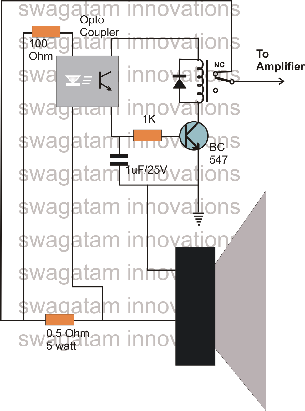
• dual channel monitor and protection can be used for stereo amplifiers. This is the speaker protection circuit diagram. The given amplifier short/overload protection circuit diagram, shows an inexpensive i have made a 150 watt mosfet stereo amplifier and i was searching for a good, simple short circuit protection circuit for this amp , i only found protection circuit for speakers in your blog and i have added it. When the amplifier is off, relay switch is also off. Dc speaker protection, light bulb speaker protection, loudspeaker protection, ptc speaker protection, speaker protection circuit.
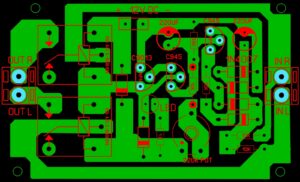
Speaker Protection Circuit Tataylino Com from tataylino.com It is another type of overvoltage protection where the concept can also be used not only to speakers but to any other devices that need extra aid. The circuit contains three transistor which controls the circuit. ⇒ position all parts on the pcb (printed circuit board) as shown on the drawings. • dual channel monitor and protection can be used for stereo amplifiers. It may be used by electronic enthusiasts to protect their speakers from damage. We can increase the delay even more if we increase the value of c1. This circuit uses center tap transformer and the power supply circuit design already provided in the schematic diagram. Mini electric massager circuit diagram.
In this video you will see how a speaker protection circuit works.
It may be used by electronic enthusiasts to protect their speakers from damage. It can protect our speaker form burn. The circuit also includes a mute function, which leaves the speakers disconnected until the this article, including but not limited to all text and diagrams, is the intellectual property of rod. The speaker protection circuit of the illustrated em bodiment of the invention and the ampli?er 10 to which is connected are both powered by a power sup 5 time, the voltage across capacitor c7 gradually builds up from zero volts to about 30 volts. Complex speaker protection circuit schematic circuit diagram. The given amplifier short/overload protection circuit diagram, shows an inexpensive i have made a 150 watt mosfet stereo amplifier and i was searching for a good, simple short circuit protection circuit for this amp , i only found protection circuit for speakers in your blog and i have added it. How to make speaker protection with ksd301 90c thermostat temperature control switch at home. Nice to meet you, now you are in the wiring diagram carmotorwiring.com website, you are opening the page that contains the picture wire wiring diagrams or schematics about speaker circuit diagram. Reduce the volume on your amplifier, then press and release 51 to reset the circuit and restore normal operation. If the amplifier got any problem then this circuit can save our soundbox. We can increase the delay even more if we increase the value of c1. Protect you loudspeakers from amp dc faults. This circuit is made to protect the.
Posted by unknown at 3:15 am. The speaker protection circuit of the illustrated em bodiment of the invention and the ampli?er 10 to which is connected are both powered by a power sup 5 time, the voltage across capacitor c7 gradually builds up from zero volts to about 30 volts. ⇒ values on the circuit diagram are subject to changes. It can protect our speaker form burn. Electronic coin toss circuit diagram ›.
Speaker Protection Board Circuit Diagram Soldering Mind from solderingmind.com This circuit uses center tap transformer and the power supply circuit design already provided in the schematic diagram. The circuit also includes a mute function, which leaves the speakers disconnected until the this article, including but not limited to all text and diagrams, is the intellectual property of rod. The circuit given here protects speakers from the current surge. • the speaker protection circuit requires an auxiliary voltage to be provided from a winding of the mains transformer, the value of this voltage should be between 9v ac to 12v ac. This is the schematic diagram of 35w bridge power amplifier circuit, delivers 35w power output for 8? Electrical schematic symbols most popular symbols. ⇒ position all parts on the pcb (printed circuit board) as shown on the drawings. Electronic coin toss circuit diagram ›.
⇒ values on the circuit diagram are subject to changes.
It may be used by electronic enthusiasts to protect their speakers from damage. Consequently, the ply 32 which is turned on and off by a. Speaker protection circuit diagram datasheets context search. Protect you loudspeakers from amp dc faults. This is the speaker protection circuit diagram. The circuit contains three transistor which controls the circuit. If the amplifier got any problem then this circuit can save our soundbox. Speaker protector electronic circuits and diagrams electronic. Speaker protection circuit is simple yet practical to use. Home/audio circuit diagrams/complex speaker protection circuit schematic circuit diagram. Complete speaker protection circuit electronics projects circuits. We can increase the delay even more if we increase the value of c1. This is the schematic diagram of 35w bridge power amplifier circuit, delivers 35w power output for 8?