Home
› Capacitor Start Motor Wiring Diagram / Single Phase Motor Wiring Diagram With Capacitor | Wiring Diagram - Each component ought to be placed and linked to different parts in particular manner.
Capacitor Start Motor Wiring Diagram / Single Phase Motor Wiring Diagram With Capacitor | Wiring Diagram - Each component ought to be placed and linked to different parts in particular manner.
Capacitor Start Motor Wiring Diagram / Single Phase Motor Wiring Diagram With Capacitor | Wiring Diagram - Each component ought to be placed and linked to different parts in particular manner.. Capacitor start motor wiring diagram source: The auxiliary circuit is opened by the centrifugal switch when the motor reaches 70 to 80 percent of synchronous speed. Wiring diagram will come with numerous easy to follow wiring diagram directions. Print the electrical wiring diagram off plus use highlighters to trace the circuit. For example , if a module is powered up also it sends out the signal of 50 percent the voltage and the technician will not know this, he would think he provides an issue.
To complete a single phase motor direction change, you will need to motors go in forward and reverse depending on their wiring and the resulting magnetic field. One trick that we use is to print out a similar wiring plan off twice. Motor start capacitors are used during startup phase of ac induction motors. When you use your finger or even follow the circuit with your eyes, it may be easy to mistrace the circuit. These instructions will probably be easy to comprehend and implement.
Fig.13 capacitor start capacitor run motor wiring diagram | Electrical A2Z from electricala2z.com Print the electrical wiring diagram off plus use highlighters to trace the circuit. Wholefoodsonabudget.com capacitor start motor wiring diagram source: If not, the structure will not work as it should be. Here are some sample capacitor installation instructions for adding a motor starter capacitor to an air conditioning. Capacitor run capacitor start motor wiring diagram from electricalvoice.com to properly read a wiring diagram, one provides to know how the components within the program operate. Read all about the capacitor circuit diagram of motor start and motor run capacitor. Single phase motor wiring diagram with capacitor start motorceowall com. To complete a single phase motor direction change, you will need to motors go in forward and reverse depending on their wiring and the resulting magnetic field.
Diagram cc motor wiring full version hd quality qdiagram andrearossato it.
An induction motor is one of type of ac motor that is supplied by means of electromagnetic induction. Best tricks and techniques in home cabling. Each component ought to be placed and linked to different parts in particular manner. Ac capacitor cost and replacement ultimate guide pickhvac. Wire start capacitor start relay black wire contactor yellow wire to run capacitor c blue wire to run capacitor herm run capacitor. Capacitor start motor wiring diagram : Single phase motor wiring diagram with capacitor start. Here are some sample capacitor installation instructions for adding a motor starter capacitor to an air conditioning. You will see that one end of the run winding and one end of the capacitor is connected to the active or live. Ask that they not flip any breakers or switches until you are finished. Each part ought to be placed and linked to different parts in particular manner. The highest reading you obtained is the starting winding and the lower reading is the running winding. The capacitor start capacitor run motor has a cage rotor and its stator has two windings known as main and auxiliary windings.
Single phase motor wiring diagram with capacitor start. Ask that they not flip any breakers or switches until you are finished. To reverse rotation on a single phase capacitor start. Motor start capacitors are used during startup phase of ac induction motors. The auxiliary circuit is opened by the centrifugal switch when the motor reaches 70 to 80 percent of synchronous speed.
Single Phase Capacitor Start and Capacitor Run Electric Motor Control-A basic industrial process ... from 3.bp.blogspot.com For instance , if a module will be powered up also it sends out a new signal of half the voltage in addition to the technician does not know this, he would think he. Starting purpose capacitor is of electrolytic type and is disconnected from the supply when the motor attains 75% of synchronous speed with the help of centrifugal switch s, connected in series with c s. It shows the elements of the circuit as simplified shapes, and the power and signal links between the tools. Read all about the capacitor circuit diagram of motor start and motor run capacitor. Now look at the connection based on the diagram below: Best tricks and techniques in home cabling. However, this motor is expensive because this motor use centrifugal. A wiring diagram is a streamlined conventional photographic representation of an electrical circuit.
Capacitor start/capacitor run induction motor.
Each component ought to be placed and linked to different parts in particular manner. To reverse rotation on a single phase capacitor start. Psc motor typical wiring diagram for a psc motor definition and characteristics. Frequent stop/starts and/or changing of the direction of rotation will damage the motor's capacitor's and winding. 120v ac capacitor motor reversing switch wiring diagram. It is intended to help all the typical user in building a correct program. Capacitor wiring diagram for electric motor from i.pinimg.com effectively read a wiring diagram, one offers to find out how typically the components within the method operate. Print the electrical wiring diagram off plus use highlighters to trace the circuit. Electrolytic capacitor c is connected in series with the starting winding along with. Ask that they not flip any breakers or switches until you are finished. Starting purpose capacitor is of electrolytic type and is disconnected from the supply when the motor attains 75% of synchronous speed with the help of centrifugal switch s, connected in series with c s. These instructions will probably be easy to comprehend and implement. Split phase capacitor start electric motor.
If not, the structure will not work as it should be. These instructions will probably be easy to comprehend and implement. For diy electricians, there's a lot of jumbled up information of what you need to or should not do. How to hook up an electric motor start or run capacitor: Starting purpose capacitor is of electrolytic type and is disconnected from the supply when the motor attains 75% of synchronous speed with the help of centrifugal switch s, connected in series with c s.
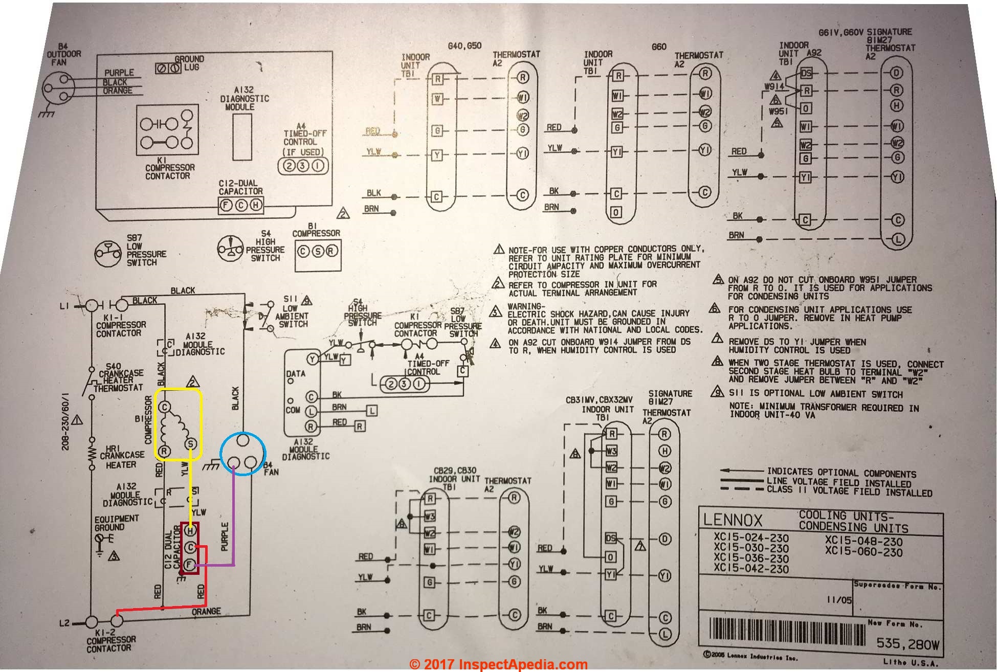
Capacitor Start Motor Wiring Diagram Craftsman - Wiring Diagram Schemas from inspectapedia.com Installation instructions start capacitor & relay kit 482 01 5130 02 3 figure 2 start capacitor & relay wiring a96112 11 21 blk c r s comp yel h 23 yel 23 cont c cap blu 5 sr 2 blk cont yel 120v ac capacitor motor reversing switch wiring diagram. Wholefoodsonabudget.com capacitor start motor wiring diagram source: When you use your finger or even follow the circuit together with your eyes, it is easy to mistrace the circuit. Motor start capacitors are used during startup phase of ac induction motors. For instance , if a module will be powered up also it sends out a new signal of half the voltage in addition to the technician does not know this, he would think he. Print the electrical wiring diagram off plus use highlighters to trace the circuit. Capacitor start motor wiring diagram :
Capacitor start motor wiring diagram :
For diy electricians, there's a lot of jumbled up information of what you need to or should not do. An induction motor is one of type of ac motor that is supplied by means of electromagnetic induction. Psc motor typical wiring diagram for a psc motor definition and characteristics. How to hook up an electric motor start or run capacitor: Single phase capacitor start motor wiring diagram. Electrolytic capacitor c is connected in series with the starting winding along with. Print the electrical wiring diagram off in addition to use highlighters to be able to trace the signal. To complete a single phase motor direction change, you will need to motors go in forward and reverse depending on their wiring and the resulting magnetic field. When a capacitor is so introduced, the voltage lags the current by some phase angle. Capacitor run capacitor start motor wiring diagram from electricalvoice.com to properly read a wiring diagram, one provides to know how the components within the program operate. One trick that i use is to printing a similar wiring diagram off twice. When you use your finger or even follow the circuit with your eyes, it may be easy to mistrace the circuit. Each part ought to be placed and linked to different parts in particular manner.